- General stress analysis
- Graphical and numerical results of stresses and stress ratios fully integrated in RFEM
- Flexible design with different layer compositions
- High efficiency due to few entries required
- Flexibility due to detailed setting options for basis and extent of calculations
- A local overall stiffness matrix of the surface in RFEM is generated on the basis of the selected material model and the layers contained. The following material models are available:
- Orthotropic
- Isotropic
- User-defined
- Hybrid (for combinations of material models)
- Option to save frequently used layer structures in a database
- Determination of basic, shear, and equivalent stresses
- In addition to the basic stresses, the required stresses according to DIN EN 1995-1-1 and the interaction of those stresses are available as results.
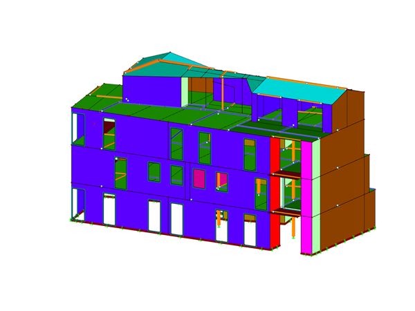
- Stress analysis for structural surfaces including simple or complex shapes
- Equivalent stresses calculated according to different approaches:
- Shape modification hypothesis (von Mises)
- Shear stress hypothesis (Tresca)
- Normal stress hypothesis (Rankine)
- Principal strain hypothesis (Bach)
- Calculation of transversal shear stresses according to Mindlin or Kirchhoff, or user-defined specifications
- Serviceability limit state design by checking surface displacements
- User-defined specifications of limit deflections
- Possibility to consider layer coupling
- Detailed results of individual stress components and ratios in tables and graphics
- Results of stresses for each layer in the model
- Parts list of designed surfaces
- Possible coupling of layers entirely without shear
RF-LAMINATE | Features

Do you have any questions?


Length: 00:00:55 min
.png?mw=350&hash=c6c25b135ffd26af9cd48d77813d2ba5853f936c)
Length: 00:08:02 min
Length: 00:00:00 min
Length: 00:00:39 min
Length: 00:00:30 min
Length: 00:00:24 min
Length: 00:00:32 min
Length: 00:00:36 min


This article describes and explains the influence of bending stiffness of cables on their internal forces. Furthermore, the text provides information on how this influence can be reduced.
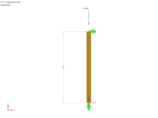
Using the Timber Design add-on, timber column design is possible according to the 2018 NDS standard ASD method. Accurately calculating timber member compressive capacity and adjustment factors is important for safety considerations and design. The following article will verify the maximum critical buckling strength calculated by the Timber Design add-on using step-by-step analytical equations as per the NDS 2018 standard including the compressive adjustment factors, adjusted compressive design value, and final design ratio.
RWIND 2 is a program for generating wind loads based on CFD (Computational Fluid Dynamics). The wind flow numerical simulation is generated around any building, including irregular or unique geometry types, to determine the wind loads on surfaces and members. RWIND 2 can be integrated with RFEM/RSTAB for the structural analysis and design or as a stand-alone application.

This article describes the development of the Parametric FEM Toolbox and some of the possible workflows with this new tool.


![Reduction of Building to Cantilever Structure: The individual mass points represent the floors. The deflection due to the normal compression forces shown in (a) is (b) converted into equivalent moments of displacement or shear forces [2].](/en/webimage/009762/2420261/01-en-png-12-png.png?mw=350&hash=dd36dc43123116724231958668ad6cdcb13a0169)


The results of solid stresses can be displayed as colored 3D points in the finite elements.
.png?mw=512&hash=ea9bf0ab53a4fb0da5c4ed81d32d53360ab2820c)
The number of degrees of freedom in a node is no longer a global calculation parameter in RFEM (6 degrees of freedom for each mesh node in 3D models, 7 degrees of freedom for the warping torsion analysis). Thus, each node is generally considered with a different number of degrees of freedom, which leads to a variable number of equations in the calculation.
This modification speeds up the calculation, especially for models where a significant reduction of the system could be achieved (for example, trusses and membrane structures).

Display extended strains of members, surfaces, and solids (for example, the important principal strains, equivalent total strains, and so on) in the Project Navigator - Results in RFEM as well as in Table 4.0.
For example, you can display governing plastic strains when performing the plastic design of connections with surface elements.

RFEM and RSTAB models can be saved as 3D glTF models (*.glb and *.glTF formats). View the models in 3D in detail with a 3D viewer from Google or Babylon. Take your VR glasses, such as Oculus, to "walk" through the structure.
You can integrate the 3D glTF models into your own websites using JavaScript according to these instructions (as on the Dlubal website Models to Download).
Can I display node coordinates in my model?
Can I use SHAPE-THIN 9 in combination with RSTAB 8?
Has the RF-TOWER add-on module for RFEM 5 already been added to RFEM 6?
RFEM calculates more slowly on my new computer than on the old one. What might be the cause, and how can I change it?
Where can I find my customer number in RFEM or RSTAB?
Is it possible to define member nonlinearities for beam members?
For example, can I define a member that absorbs all internal forces, except for the compressive axial forces?
For example, can I define a member that absorbs all internal forces, except for the compressive axial forces?


.jpg?mw=350&hash=8f312d6c75a747d88bf9d0f5b1038595900b96c1)

Recommended Products for You
RFEM 6 | Main Program RFEM 6

The new generation of 3D FEA software is used for the structural analysis of members, surfaces, and solids.
Price of First License
4,170.00 USD
RFEM 6 | Special Solutions
The Multilayer Surfaces add-on allows you to define multilayer surface structures. The calculation can be carried out with or without the shear coupling.
Price of First License
1,300.00 USD
RFEM 6 | Design
The Timber Design add-on performs the ultimate, serviceability, and fire resistance limit state design checks of timber members according to various standards.
Price of First License
1,930.00 USD
RSTAB 9 | Main Program RSTAB 9

The modern 3D structural analysis and design program is suitable for the structural and dynamic analysis of beam structures as well as the design of concrete, steel, timber, and other materials.
Price of First License
2,910.00 USD
RSTAB 9 | Design
The Timber Design add-on performs the ultimate, serviceability, and fire resistance limit state design checks of timber members according to various standards.
Price of First License
1,930.00 USD
RFEM 5 | Main Program RFEM

Structural engineering software for a finite element analysis (FEA) of planar and spatial structural systems consisting of plates, walls, shells, members (beams), solids, and contact elements
Price of First License
4,080.00 USD
RFEM 5 | Other

Deflection analysis and stress design of laminate and sandwich surfaces
Price of First License
1,300.00 USD
RFEM 5 | Timber Structures

Timber design according to Eurocode 5, SIA 265, and/or DIN 1052
Price of First License
1,750.00 USD
RFEM 5 | Timber Structures

Design of timber members according to the American standard ANSI/AWC NDS
Price of First License
1,750.00 USD
RFEM 5 | Timber Structures

Design of timber members according to the Canadian standard CSA O86-14
Price of First License
1,750.00 USD
RFEM 5 | Timber Structures

Design of timber members according to the Brazilian standard NBR 7190:1997
Price of First License
1,750.00 USD
RFEM 5 | Timber Structures

Design of timber members according to the South African standards SANS 10163-1:2003 and SANS 10163-2:2001
Price of First License
1,750.00 USD
RSTAB 8 | Timber Structures

Timber design according to Eurocode 5, SIA 265 and/or DIN 1052
Price of First License
1,930.00 USD
RSTAB 8 | Timber Structures

Design of timber members according to the American standard ANSI/AWC NDS
Price of First License
1,930.00 USD
RSTAB 8 | Timber Structures

Design of timber members according to the Canadian standard CSA O86-14
Price of First License
1,930.00 USD
RSTAB 8 | Timber Structures

Design of timber members according to the Brazilian standard NBR 7190:1997
Price of First License
1,930.00 USD
RSTAB 8 | Timber Structures

Design of timber members according to the South African standards SANS 10163-1:2003 and SANS 10163-2:2001
Price of First License
1,930.00 USD
RX-TIMBER 2 | Timber Structures

Timber design of single-span and wide-span glulam beams according to Eurocode 5 or DIN 1052
Price of First License
1,120.00 USD