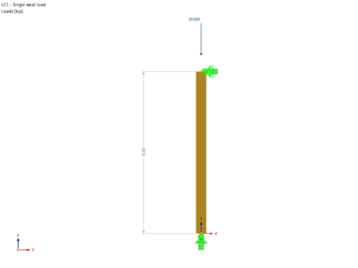
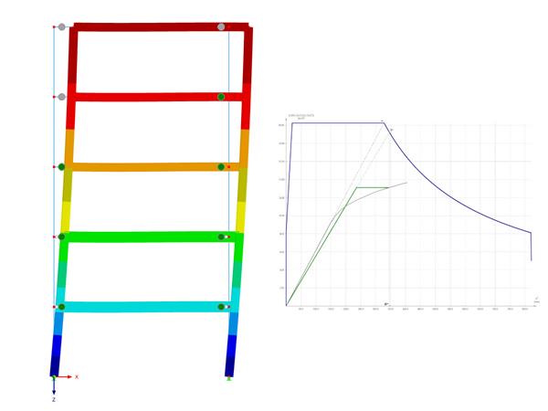
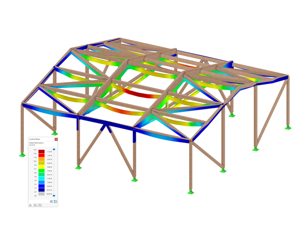
In most cases, the default setting "Shifted member ends/set of member ends" is suitable for considering the displacements of the total structural system in the design. For the beam shown in the figure, however, the reference length has been changed manually to the span between the supports. In this case, the deformation must be related to the undeformed system in order for the correct deflection to be integrated in the design.
Relation of Deformations
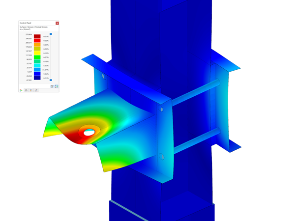
Not only do RF-/STEEL EC3 and RF-/TIMBER Pro perform cross-section designs and stability analyses, they allow you to perform serviceability limit state designs. For this, it is possible to relate the deformation to the undeformed initial system or to shifted members ends.
Author
Mr. Vogl creates and maintains the technical documentation.
Links
Do you have any questions?


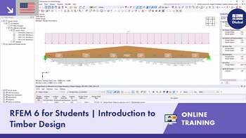
Length: 01:08:12 min

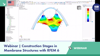
Length: 00:58:00 min

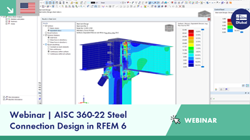
Length: 01:04:39 min

Length: 00:55:53 min
Length: 01:08:02 min
Length: 01:02:19 min
Length: 01:02:00 min
Length: 00:01:22 min

Length: 01:01:43 min


Not only do RF-/STEEL EC3 and RF-/TIMBER Pro perform cross-section designs and stability analyses, they allow you to perform serviceability limit state designs. For this, it is possible to relate the deformation to the undeformed initial system or to shifted members ends.

In this article, the calculation of a timber panel wall with the beam panel thickness type is compared with a manual calculation.
Using the Timber Design add-on, timber column design is possible according to the 2018 NDS standard ASD method. Accurately calculating timber member compressive capacity and adjustment factors is important for safety considerations and design. The following article will verify the maximum critical buckling strength calculated by the Timber Design add-on using step-by-step analytical equations as per the NDS 2018 standard including the compressive adjustment factors, adjusted compressive design value, and final design ratio.
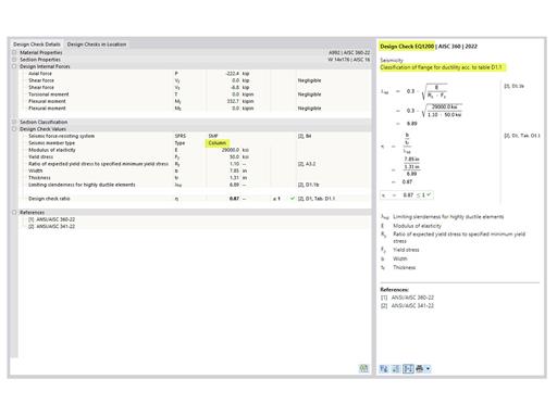
The three types of moment frames (Ordinary, Intermediate, Special) are available in the Steel Design add-on of RFEM 6. The seismic design result according to AISC 341-22 is categorized into two sections: member requirements and connection requirements.


.JPG?mw=350&hash=d57486d45e0440dd9a6be9be91368a3e4f42f4b9)
.JPG?mw=350&hash=df48834f2d658081d5f412d698c4da41b73309b9)

In RFEM, the oriented strand board (OSB) material is available for the USA and Canada. The material parameters are taken from the "Panel Design Specification manual".

In the ultimate configuration of the steel joint design, you have the option to modify the limit plastic strain for welds.

The "Base Plate" component allows you to design base plate connections with cast-in anchors. In this case, plates, welds, anchorages, and steel-concrete interaction are analyzed.
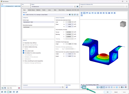
In the "Edit Section" dialog box, you can display the buckling shapes of the Finite Strip Method (FSM) as a 3D graphic.
Why do the results of members and sets of members differ in the design?
In the case of the serviceability limit state design (for example, of a steel beam), the precamber is not taken into account. Is this a program error or is my entry incorrect?
How can I reduce the calculation time for members with a nonlinear material model in RFEM 6 and RSTAB 9?
Why are the stresses of the structural analysis different from those calculated with the Stress-Strain Analysis add-on?
Is it possible to use the general method according to EN 1993‑1‑1, 6.3.4 to design structural components with an asymmetric cross-section in the Steel Design add-on for RFEM 6 or RSTAB 9?
How can the NDS and CSA O86 factors be manually adjusted for consideration in the Timber Design add-on?


.jpg?mw=350&hash=91f398b559b26a6ac36fd7ecdf5e395e7b9b856d)


Recommended Products for You
RFEM 6 | Main Program RFEM 6

The new generation of 3D FEA software is used for the structural analysis of members, surfaces, and solids.
Price of First License
4,170.00 USD
RFEM 6 | Design
The Steel Design add-on performs the ultimate and serviceability limit state design checks of steel members according to various standards.
Price of First License
2,550.00 USD
RFEM 6 | Joints
.png?mw=600&hash=49b6a289915d28aa461360f7308b092631b1446e)
The Steel Joints add-on for RFEM allows you to analyze steel connections using an FE model. The FE model is generated automatically in the background and can be controlled via the simple and familiar input of components.
Price of First License
2,110.00 USD
RFEM 6 | Additional Analysis

The Torsional Warping (7 DOF) add-on allows you to consider cross-section warping as an additional degree of freedom.
Price of First License
1,480.00 USD
RFEM 6 | Additional Analysis

The Nonlinear Material Behavior add-on allows you to consider material nonlinearities in RFEM for example, isotropic plastic, orthotropic plastic, isotropic damage).
Price of First License
1,480.00 USD
RFEM 6 | Additional Analysis
The Structure Stability add-on performs stability analysis of structures. It determines critical load factors and the corresponding stability modes.
Price of First License
1,300.00 USD
RFEM 6 | Additional Analysis

The Construction Stages Analysis (CSA) add-on allows for considering the construction process of structures (member, surface, and solid structures) in RFEM.
Price of First License
1,570.00 USD
RFEM 6 | Additional Analysis
The Time-Dependent Analysis (TDA) add-on allows you to consider the time-dependent material behavior of members. The long-term effects, such as creep, shrinkage, and aging, can influence the distribution of internal forces, depending on the structure.
Price of First License
1,030.00 USD
RFEM 6 | Additional Analysis
The Form-Finding add-on finds the optimal shape of members subjected to axial forces and tension-loaded surface models. The shape is determined by the equilibrium between the member axial force or the membrane stress and the existing boundary conditions.
Price of First License
2,060.00 USD
RFEM 6 | Dynamic Analysis

The Modal Analysis add-on allows for the calculation of eigenvalues, natural frequencies, and natural periods for member, surface, and solid models.
Price of First License
1,210.00 USD
RFEM 6 | Dynamic Analysis
Using the Pushover Analysis add-on, you can analyze the seismic actions on a particular building, and thus assess whether the building can withstand an earthquake.
Price of First License
1,300.00 USD
RFEM 6 | Special Solutions

The Building Model add-on for RFEM allows you to define and manipulate a building using stories. The stories can be adjusted in many ways afterwards. The information about stories and the entire model (center of gravity) is displayed in tables and graphics.
Price of First License
1,660.00 USD
RFEM 6 | Design
The Stress-Strain Analysis add-on performs general stress analysis by calculating the existing stresses and comparing them with the limit stresses.
Price of First License
1,210.00 USD
RSTAB 9 | Main Program RSTAB 9

The modern 3D structural analysis and design program is suitable for the structural and dynamic analysis of beam structures as well as the design of concrete, steel, timber, and other materials.
Price of First License
2,910.00 USD
RSTAB 9 | Design
The Steel Design add-on performs the ultimate and serviceability limit state design checks of steel members according to various standards.
Price of First License
2,550.00 USD
RSTAB 9 | Additional Analysis
The Structure Stability add-on performs the stability analysis of structures. It determines critical load factors and the corresponding stability modes.
Price of First License
1,300.00 USD
RSTAB 9 | Design
The Stress-Strain Analysis add-on performs a general stress analysis by calculating the existing stresses and comparing them to the limit stresses.
Price of First License
1,120.00 USD
RSTAB 9 | Additional Analysis
The Torsional Warping (7 DOF) add-on allows for considering cross-section warping as an additional degree of freedom when calculating members.
Price of First License
1,480.00 USD
RSTAB 9 | Dynamic Analysis
The Modal Analysis add-on allows for the calculation of eigenvalues, natural frequencies, and natural periods for member, surface, and solid models.
Price of First License
1,210.00 USD
RSTAB 9 | Dynamic Analysis
Earthquakes may have a significant impact on the deformation behavior of buildings. A pushover analysis allows you to analyze the deformation behavior of buildings and compare them with seismic actions. Using the Pushover Analysis add-on, you can analyze the seismic actions on a particular building, and thus assess whether the building can withstand the earthquake.
Price of First License
1,300.00 USD
RFEM 6 | Design
The Timber Design add-on performs the ultimate, serviceability, and fire resistance limit state design checks of timber members according to various standards.
Price of First License
1,930.00 USD
RSTAB 9 | Design
The Timber Design add-on performs the ultimate, serviceability, and fire resistance limit state design checks of timber members according to various standards.
Price of First License
1,930.00 USD
RX-TIMBER 2 | Timber Structures

Timber design of single-span and wide-span glulam beams according to Eurocode 5 or DIN 1052
Price of First License
1,120.00 USD
RX-TIMBER 2 | Timber Structures

Timber design of simple, continuous, and Gerber beams with or without cantilever according to Eurocode 5 or DIN 1052
Price of First License
360.00 USD
RX-TIMBER 2 | Timber Structures

Timber design of rectangular and circular columns according to Eurocode 5 or DIN 1052
Price of First License
360.00 USD
RX-TIMBER 2 | Timber Structures

Timber design of coupled purlins and continuous beams according to Eurocode 5 or DIN 1052
Price of First License
360.00 USD
RX-TIMBER 2 | Timber Structures

Timber design of three-hinged frames with finger joint connections according to Eurocode 5 or DIN 1052
Price of First License
360.00 USD
RX-TIMBER 2 | Timber Structures

Timber design of stiffening truss bracing according to Eurocode 5 or DIN 1052
Price of First License
360.00 USD
RX-TIMBER 2 | Timber Structures

Timber design of flat, monopitch, and duopitch roofs according to Eurocode 5
Price of First License
360.00 USD