Answer:
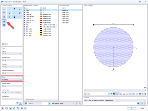
You can usually set the standard and the National Annex in the top right corner of an add‑on module or a stand-alone program (see Image 01). In most cases, it is also possible to display the factors of the National Annex and edit them, if necessary (see Image 02).
Question
How can I change the Standard / National Annex set for the design in the add-on modules and stand-alone programs?


- Add-on Modules
- CONCRETE 8
- ALUMINUM 8
- CONCRETE Columns 8
- EC2 for RFEM 5
- EC2 for RSTAB 8
- TIMBER Pro 8
- CRANEWAY 8
- RF-CONCRETE Columns 5
- RF-CONCRETE 5
- RF-PLATE-BUCKLING 5
- RF-FOUNDATION Pro 5
- RF-HSS 5
- RF-GLASS 5
- RF-TIMBER Pro 5
- RF-SOILIN 5
- RF-FRAME-JOINT Pro 5
- RF-STEEL EC3 5
- RF-PUNCH Pro 5
- Eurocode 2
- Eurocode 3
- Eurocode 5
- Eurocode 9
- Eurocode 7
Do you have any questions?


Length: 00:58:00 min
Length: 01:08:02 min
Length: 01:02:19 min
Length: 00:52:59 min
Length: 00:00:56 min

Length: 00:50:32 min
Length: 01:09:36 min
Length: 00:55:27 min
Length: 00:00:53 min


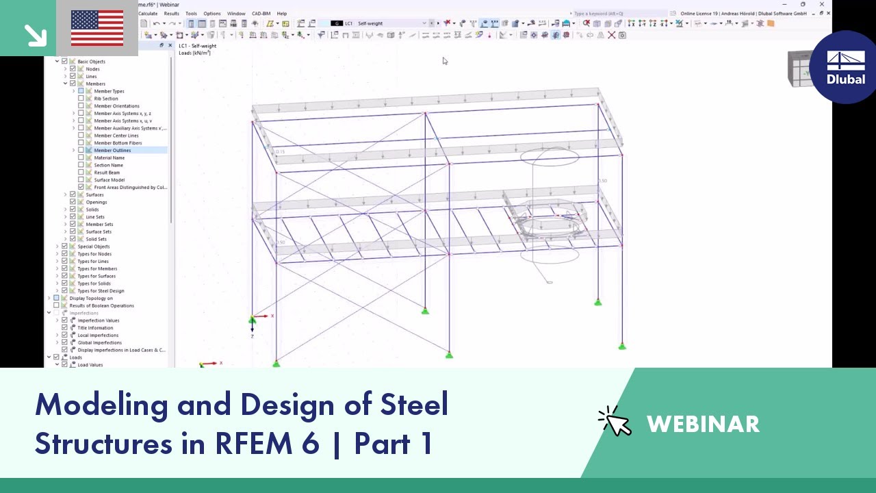
In this article, you will learn how to model and design cable structures in RFEM 6 or RSTAB 9.
This article describes and explains the influence of bending stiffness of cables on their internal forces. Furthermore, the text provides information on how this influence can be reduced.
The fatigue design according to EN 1992-1-1 must be performed for the structural components subjected to large stress ranges and/or many load changes. In this case, the design checks for the concrete and the reinforcement are performed separately. There are two alternative design methods available.
![Spans Based on Figure 5.2 from [1]](/en/webimage/039540/3493372/01_Abmessungen_EN.png?mw=512&hash=3cc425f1463bd5981b358d5889e3109e07ae1233)
In order to correctly design a downstand beam or a T-beam in RFEM 6 using the Concrete Design add-on, it is essential to determine the flange widths for the rib members. This article describes the input options for a two-span beam and the calculation of the flange dimensions according to EN 1992-1-1.


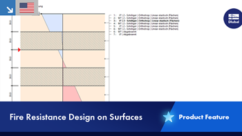
You have the option to perform the fire resistance design of surfaces using the reduced cross-section method. The reduction is applied over the surface thickness. It is possible to perform the design checks for all timber materials allowed for the design.
For cross-laminated timber, depending on the type of adhesive, you can select whether it is possible for individual carbonized layer parts to fall off, and whether you can expect increased charring in certain layer areas.
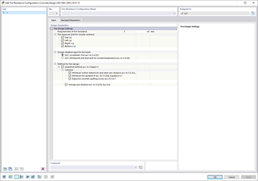
The Concrete Design add-on provides you with the option to perform the simplified fire resistance design according to EN 1992‑1‑2 for columns (Section 5.3.2) and beams (Section 5.6).
The following design checks are available for the simplified fire resistance design:
- Columns: Minimum cross-sectional dimensions for rectangular and circular sections according to Table 5.2a as well as Equation 5.7 for calculating time of fire exposure
- Beams: Minimum dimensions and center distances according to Table 5.5 and Table 5.6
You can determine the internal forces for the fire resistance design according to two methods.
- 1 Here, the internal forces of the accidental design situation are included directly into the design.
- 2 The internal forces of the design at normal temperature are reduced by the factor Eta,fi (ηfi), then used in the fire resistance design.
Furthermore, it is possible to modify the axis distance according to Eq. 5.5.
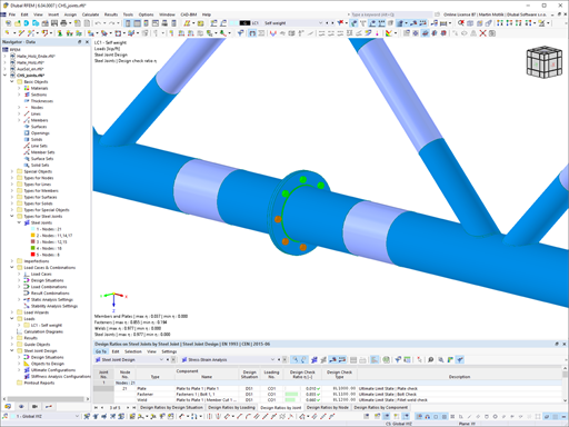
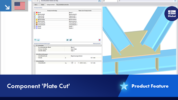
The Steel Joints add-on provides you with the option to connect circular hollow sections using welds.
It is possible to connect the circular sections to each other or to planar structural components. The fillets of standard and thin-walled sections can also be connected with a weld.
Go to Explanatory Video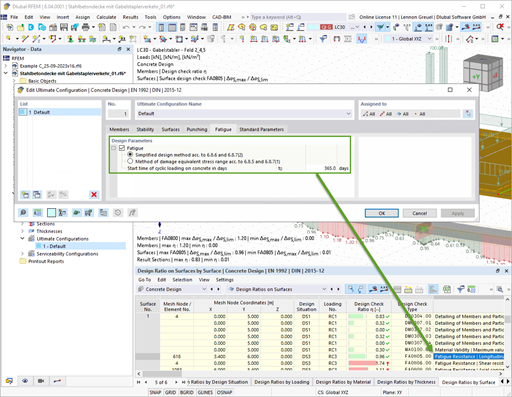
With the Concrete Design add-on, you can perform the fatigue design of members and surfaces according to EN 1992‑1‑1, Chapter 6.8.
For the fatigue design, you can optionally select two methods or design levels in the design configurations:
- Design Level 1: Simplified design according to 6.8.6 and 6.8.7(2): The simplified design is performed for frequent action combinations according to EN 1992‑1‑1, Chapter 6.8.6 (2), and EN 1990, Eq. (6.15b) with the traffic loads relevant in the serviceability state. A maximum stress range according to 6.8.6 is designed for the reinforcing steel. The concrete compressive stress is determined by means of the upper and lower allowable stress according to 6.8.7(2).
- Design Level 2: Design of damage equivalent stress acc. to 6.8.5 and 6.8.7(1) (simplified fatigue design): The design using damage equivalent stress ranges is performed for the fatigue combination according to EN 1992‑1‑1, Chapter 6.8.3, Eq. (6.69) with the specifically defined cyclic action Qfat.
How can I change the Standard / National Annex set for the design in the add-on modules and stand-alone programs?
Is it possible to use the general method according to EN 1993‑1‑1, 6.3.4 to design structural components with an asymmetric cross-section in the Steel Design add-on for RFEM 6 or RSTAB 9?
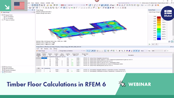
Which Dlubal software products do you recommend for the structural analysis and design of timber structures in particular?
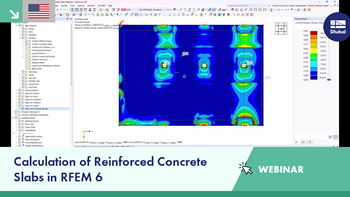
Which products do you recommend for the structural analysis and design of reinforced concrete structures?
In the Steel Design add-on, I have set the boundary conditions in such a way that the I-beam flange is restrained against the horizontal displacement. I then calculated the critical load factors using the Structure Stability add-on, but with no effect on the critical load factor value. What is the reason for this?
How can I use graphic templates for multi printing of a reinforcement?

.jpg?mw=350&hash=91f398b559b26a6ac36fd7ecdf5e395e7b9b856d)


