The following points should be considered in order to use the determined internal forces for the design:
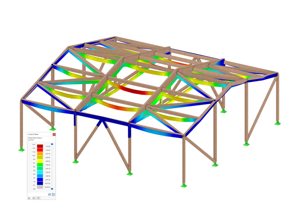
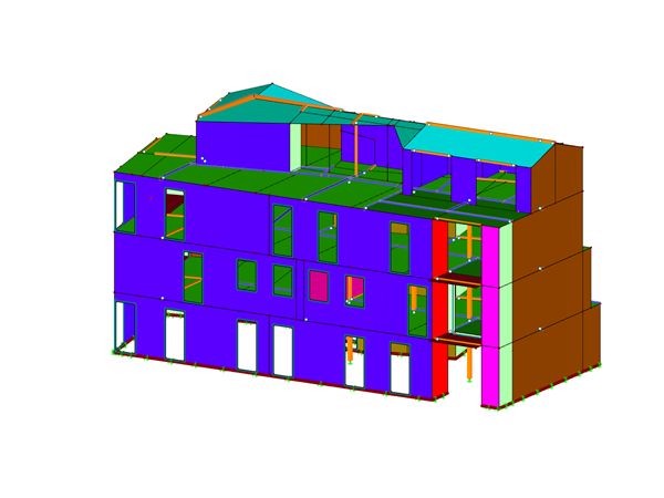
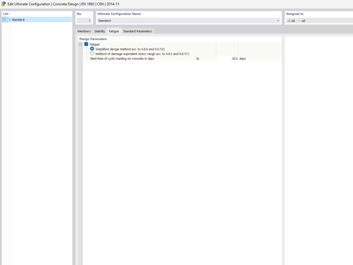
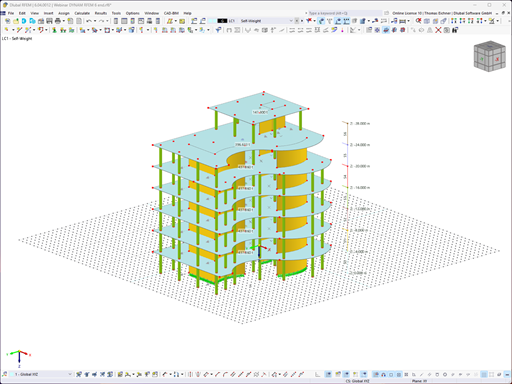
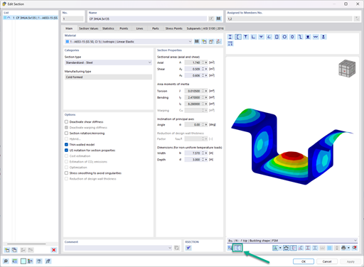
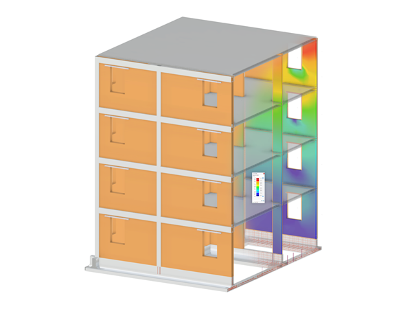
The model should represent the real structure as precisely as possible. Therefore, it is necessary to correctly define the materials, surface thicknesses, cross-section dimensions, hinge definitions, support conditions, and so on.
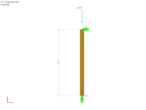
Loads must be defined and applied in compliance with the standard. RFEM can import the combinations automatically.
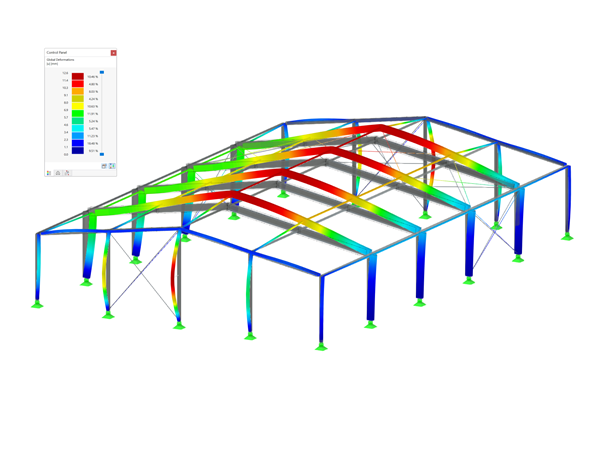
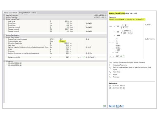
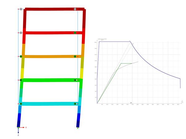
In the case of internal forces from result combinations, it is necessary to pay attention to the evaluation of the correct max/min values. The maximum compression force in a column corresponds to the minimum axial force (min N).
Question
How do I obtain the maximum column load in my RFEM 3D model?
Answer:
Do you have any questions?
Using the Timber Design add-on, timber column design is possible according to the 2018 NDS standard ASD method. Accurately calculating timber member compressive capacity and adjustment factors is important for safety considerations and design. The following article will verify the maximum critical buckling strength calculated by the Timber Design add-on using step-by-step analytical equations as per the NDS 2018 standard including the compressive adjustment factors, adjusted compressive design value, and final design ratio.
The three types of moment frames (Ordinary, Intermediate, Special) are available in the Steel Design add-on of RFEM 6. The seismic design result according to AISC 341-22 is categorized into two sections: member requirements and connection requirements.
The fatigue design according to EN 1992-1-1 must be performed for the structural components subjected to large stress ranges and/or many load changes. In this case, the design checks for the concrete and the reinforcement are performed separately. There are two alternative design methods available.
To evaluate whether it is also necessary to consider the second-order analysis in a dynamic calculation, the sensitivity coefficient of interstory drift θ is provided in EN 1998‑1, Sections 2.2.2 and 4.4.2.2. It can be calculated and analyzed using RFEM 6 and RSTAB 9.
In the ultimate configuration of the steel joint design, you have the option to modify the limit plastic strain for welds.
Using the "Base Plate" component, you can design base plate connections with cast-in anchors. In addition to plates and welds, the design analyzes the anchorage and the steel-concrete interaction.
In the "Edit Section" dialog box, you can display the buckling shapes of the Finite Strip Method (FSM) as a 3D graphic.
Do you have individual column sections and angled wall geometries, and need punching shear design for them?
No problem. In RFEM 6, you can perform punching shear design not only for rectangular and circular sections, but for any cross-section shape.
Recommended Products for You