Do you have any questions about Dlubal products or need assistance in selecting the right one for your project?
I'm here to help. You can easily reach me through the contact options provided below.
Looking forward to hearing from you!

Building Information Modeling (BIM) | Nemetschek Allplan

RFEM Interface to Nemetschek Allplan

Import in RFEM
You can import one or more surfaces to RFEM using IFC files. Thus, the structural data, such as nodes, lines, or material, are exported.
For example, you can export the floor plans as DXF and display them as a background layer in RFEM.

Export to Allplan
A reinforcement determined in RF-CONCRETE can be exported with an ASF file to Allplan. Allplan displays the reinforcement contours and FEA reinforcement color images.
If reinforcement is placed in the surface, the FEA reinforcement color images are adjusted, meaning that the reinforcement values of the placed reinforcement are substracted from the values of the required reinforcement.


Various design parameters of the cross-sections can be adjusted in the serviceability limit state configuration. The applied cross-section condition for the deformation and crack width analysis can be controlled there.
For this, the following settings can be activated:
- Crack state calculated from associated load
- Crack state determined as an envelope from all SLS design situations
- Cracked state of cross-section - independent of load

In the "Deflection and Design Support" tab under "Edit Member", the members can be clearly segmented using optimized input windows. Depending on the supports, the deformation limits for cantilever beams or single-span beams are used automatically.
By defining the design support in the corresponding direction at the member start, member end, and intermediate nodes, the program automatically recognizes the segments and segment lengths to which the allowable deformation is related. It also automatically detects whether it is a beam or a cantilever due to the defined design supports. The manual assignment, as in the previous versions (RFEM 5), is no longer necessary.
The "User-Defined Lengths" option allows you to modify the reference lengths in the table. The corresponding segment length is always used by default. If the reference length deviates from the segment length (for example, in the case of curved members), it can be adjusted.

This feature also contributes to the clearly-arranged display of your results. Clipping planes are intersecting planes that you can place freely throughout the model. The zone in front of or behind the plane is consequently hidden in the display. This way, you can clearly and simply show the results in an intersection or a solid, for example.

The results of solid stresses can be displayed as colored 3D points in the finite elements.


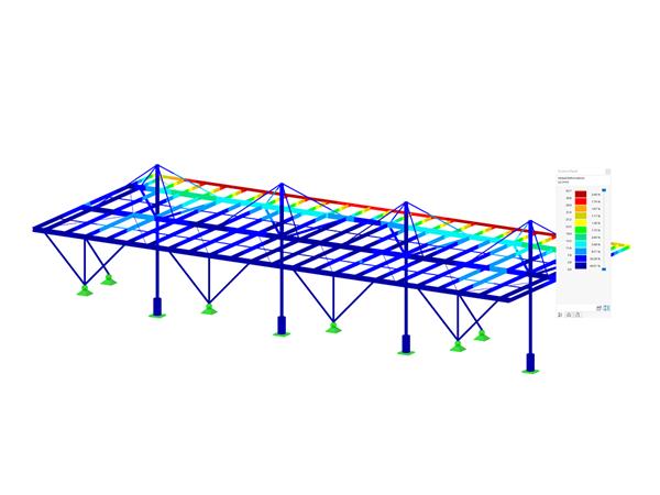
The new generation of 3D FEA software is used for the structural analysis of members, surfaces, and solids.

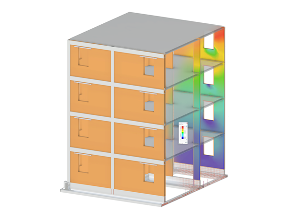
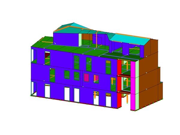
The Building Model add-on for RFEM allows you to define and manipulate a building using stories. The stories can be adjusted in many ways afterwards. The information about stories and the entire model (center of gravity) is displayed in tables and graphics.
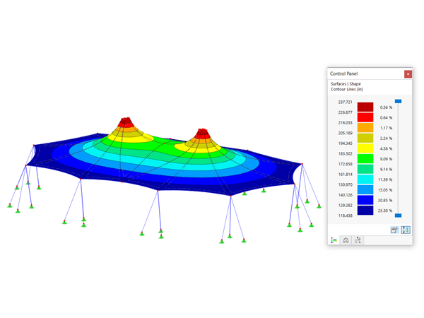
The Form-Finding add-on finds the optimal shape of members subjected to axial forces and tension-loaded surface models. The shape is determined by the equilibrium between the member axial force or the membrane stress and the existing boundary conditions.
The Masonry Design add-on for RFEM allows you to design masonry using the finite element method. It was developed as part of the research project titled DDMaS – Digitizing the Design of Masonry Structures. The material model represents the nonlinear behavior of the brick-mortar combination in the form of macro-modeling.
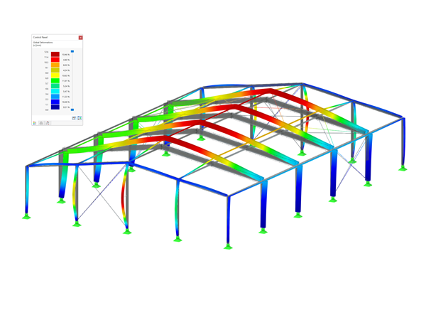
The Steel Design add-on performs the ultimate and serviceability limit state design checks of steel members according to various standards.
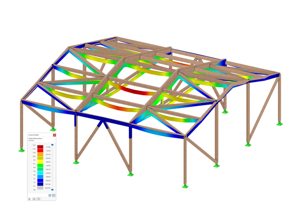
The Timber Design add-on performs the ultimate, serviceability, and fire resistance limit state design checks of timber members according to various standards.
The Multilayer Surfaces add-on allows you to define multilayer surface structures. The calculation can be carried out with or without the shear coupling.
The Aluminum Design add-on performs the ultimate and serviceability limit state design checks of aluminum members according to various standards.
.png?mw=600&hash=49b6a289915d28aa461360f7308b092631b1446e)
The Steel Joints add-on for RFEM allows you to analyze steel connections using an FE model. The FE model is generated automatically in the background and can be controlled via the simple and familiar input of components.

The Concrete Design add-on allows for various design checks according to international standards. You can design members, surfaces, and columns, as well as perform punching and deformation analyses.

The modern 3D structural analysis and design program is suitable for the structural and dynamic analysis of beam structures as well as the design of concrete, steel, timber, and other materials.
Concrete Design add-on allows for various design checks of members and columns according to international standards.
The Steel Design add-on performs the ultimate and serviceability limit state design checks of steel members according to various standards.
The Timber Design add-on performs the ultimate, serviceability, and fire resistance limit state design checks of timber members according to various standards.
The Aluminum Design add-on performs the ultimate and serviceability limit state design checks of aluminum members according to various standards.

The two-part Optimization & Costs / CO2 Emission Estimation add-on finds suitable parameters for parameterized models and blocks via the artificial intelligence (AI) technique of particle swarm optimization (PSO) for compliance with common optimization criteria. Furthermore, this add-on estimates the model costs or CO2 emissions by specifying unit costs or emissions per material definition for the structural model.
The two-part Optimization & Costs / CO2 Emission Estimation add-on finds suitable parameters for parameterized models and blocks via the artificial intelligence (AI) technique of particle swarm optimization (PSO) for compliance with common optimization criteria. Furthermore, this add-on estimates the model costs or CO2 emissions by specifying unit costs or emissions per material definition for the structural model.