.svg?mw=64&hash=343d71fbdf234f1411db2920f2dff33c0dbd6231)
.png?mw=926&hash=33da3f9402dda6d91bbb827fca94af255629fac3)
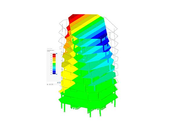
Masonry garage.
Garage
| Number of Nodes | 41 |
| Number of Lines | 49 |
| Number of Members | 12 |
| Number of Surfaces | 6 |
| Number of Solids | 0 |
| Number of Load Cases | 2 |
| Number of Load Combinations | 4 |
| Number of Result Combinations | 0 |
| Total Weight | 113.211 tons |
| Dimensions | 31.17 x 11.48 x 22.97 feet |
You can download this structural model to use it for training purposes or for your projects. However, we do not assume any guarantee or liability for the accuracy or completeness of the model.


In the ultimate configuration of the steel joint design, you have the option to modify the limit plastic strain for welds.

Using the "Base Plate" component, you can design base plate connections with cast-in anchors. In addition to plates and welds, the design analyzes the anchorage and the steel-concrete interaction.
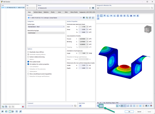
In the "Edit Section" dialog box, you can display the buckling shapes of the Finite Strip Method (FSM) as a 3D graphic.
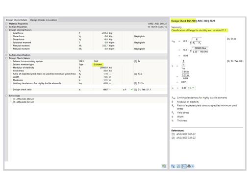
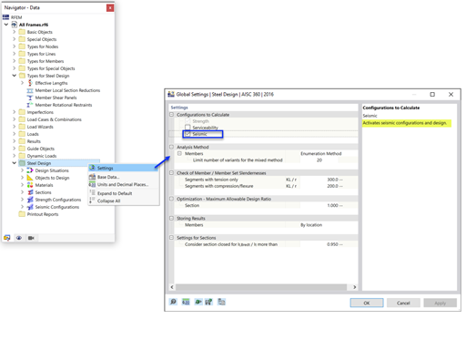
- Design of five types of seismic force-resisting systems (SFRS) includes Special Moment Frame (SMF), Intermediate Moment Frame (IMF), Ordinary Moment Frame (OMF), Ordinary Concentrically Braced Frame (OCBF), and Special Concentrically Braced Frame (SCBF)
- Ductility check of the width-to thickness ratios for webs and flanges
- Calculation of the required strength and stiffness for stability bracing of beams
- Calculation of the maximum spacing for stability bracing of beams
- Calculation of the required strength at hinge locations for stability bracing of beams
- Calculation of the column required strength with the option to neglect all bending moments, shear, and torsion for overstrength limit state
- Design check of column and brace slenderness ratios


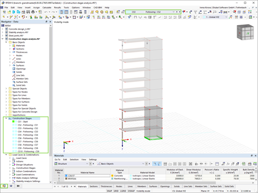
The new generation of 3D FEA software is used for the structural analysis of members, surfaces, and solids.
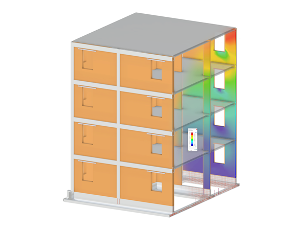
The Masonry Design add-on for RFEM allows you to design masonry using the finite element method. It was developed as part of the research project titled DDMaS – Digitizing the Design of Masonry Structures. The material model represents the nonlinear behavior of the brick-mortar combination in the form of macro-modeling.

The Nonlinear Material Behavior add-on allows you to consider material nonlinearities in RFEM for example, isotropic plastic, orthotropic plastic, isotropic damage).
The Structure Stability add-on performs stability analysis of structures. It determines critical load factors and the corresponding stability modes.

The Building Model add-on for RFEM allows you to define and manipulate a building using stories. The stories can be adjusted in many ways afterwards. The information about stories and the entire model (center of gravity) is displayed in tables and graphics.

Structural engineering software for a finite element analysis (FEA) of planar and spatial structural systems consisting of plates, walls, shells, members (beams), solids, and contact elements

Design of reinforced concrete members and surfaces (plates, walls, planar structures, shells)

Analytical deformation analysis of plate structures consisting of reinforced concrete

Physical and geometrical nonlinear calculation of beam and plate structures consisting of reinforced concrete

Consideration of nonlinear material laws