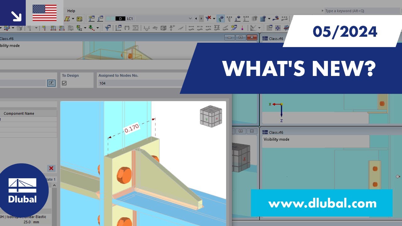
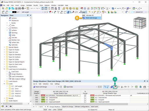
In this tutorial, we would like to inform you about the essential features of the RFEM program. In the first part, a model was defined and a structural analysis carried out. Then the concrete and steel designs were performed in the following parts. This part now deals with the design of the steel connections according to EN 1993-1-8 with the CEN settings.
Online Manuals
RFEM 6 | Tutorial - Steel Joints
RFEM 6 | Tutorial - Steel Joints

Length: 00:01:52 min
Length: 01:02:00 min

Length: 00:01:12 min

Length: 00:50:32 min
Length: 00:00:41 min

Length: 00:52:00 min

Length: 01:02:39 min
Length: 00:58:09 min

Length: 00:48:24 min


This article explains how the calculation in the initial stiffness analysis in Steel Joints works.

In this article, a lap joint of a ZL purlin on a monopitch roof is modeled and designed using the Steel Joints add-on, and compared with the load-bearing capacity table of the manufacturer.
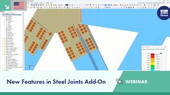
The advantage of the RFEM 6 Steel Joints add-on is that you can analyze steel connections using an FE model for which the modeling runs fully automatically in the background. The input of the steel joint components that control the modeling can be done by defining the components manually, or by using the available templates in the library. The latter method is included in a previous Knowledge Base article titled “Defining Steel Joint Components Using the Library". The definition of parameters for the design of steel joints is the topic of the Knowledge Base article “Designing Steel Joints in RFEM 6".
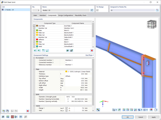
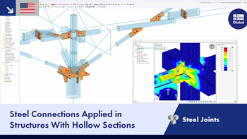
Steel connections in RFEM 6 are defined as an assembly of components. In the new Steel Joints add-on, universally applicable basic components (plates, welds, auxiliary planes) are available for entering complex connection situations. The methods with which connections can be defined are considered in two previous Knowledge Base articles: “A Novel Approach to Designing Steel Joints in RFEM 6" and “Defining Steel Joint Components Using the Library".


In the ultimate configuration of the steel joint design, you have the option to modify the limit plastic strain for welds.

The "Base Plate" component allows you to design base plate connections with cast-in anchors. In this case, plates, welds, anchorages, and steel-concrete interaction are analyzed.

Using the "Rib" component, you can define any number of longitudinal ribs on a member plate. By defining a reference object, you can automatically specify welds on it.
The "Rib" component can also be arranged on circular hollow sections. Dafür wird zusätzlich die Vorgabe der Winkel zwischen den Rippen benötigt.

You can now insert a cap plate in steel joints with only a few clicks. You can enter the data using the known definition types "Offsets" or "Dimensions and Position". By specifying a reference member and the cutting plane, it is also possible to omit the Member Section component.
This component allows you to easily model cap plates on column ends, for example.
Which programs and add-ons are suitable for the structural analysis and design of steel structures?
How do I create a splice connection in the Steel Joints add-on?
Can I exclude bolt threads from the shear planes according to AISC 360-16 in the Steel Joints Add-on?
Where can I find the materials for the corresponding National Annexes in RFEM 6 and RSTAB 9?
.jpg?mw=350&hash=91f398b559b26a6ac36fd7ecdf5e395e7b9b856d)

