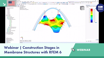
The Construction Stages Analysis (CSA) add-on allows you to represent the construction process of the model in the RFEM 6 program. In this way, you can add, remove, or adjust structural objects to the individual construction phases. Furthermore, you can use the add-on can to determine the sequence of the load application and the way how the load cases are combined within the construction stages.
Online Manuals
RFEM 6 | Construction Stages Analysis
RFEM 6 | Construction Stages Analysis


Length: 00:01:20 min

Length: 00:00:53 min

Length: 00:55:53 min
Length: 01:02:19 min
Length: 01:02:00 min

Length: 01:01:43 min

Length: 00:50:32 min
Length: 01:02:20 min
Length: 00:00:32 min


This technical article analyzes the effects of the connection stiffness on the determination of internal forces, as well as the design of connections using the example of a two-story, double-spanned steel frame.

This example is described in technical literature [1] as Example 9.5 and in [2] as Example 8.5. A lateral-torsional buckling analysis must be performed for a principal beam. This beam is a uniform structural member. Therefore, the stability analysis can be carried out according to Clause 6.3.3 of DIN EN 1993-1-1. Due to the uniaxial bending, it would also be possible to perform the design using the General Method according to Clause 6.3.4. Additionally, the determination of the moment Mcr is validated with an idealized member model in line with the method mentioned above, using an FEM model.
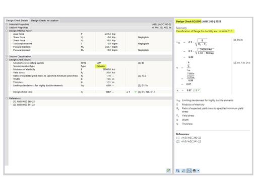
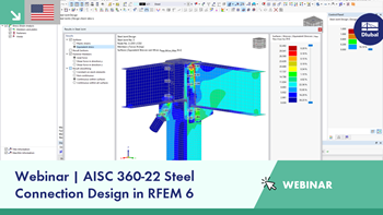
The three types of moment frames (Ordinary, Intermediate, Special) are available in the Steel Design add-on of RFEM 6. The seismic design result according to AISC 341-22 is categorized into two sections: member requirements and connection requirements.
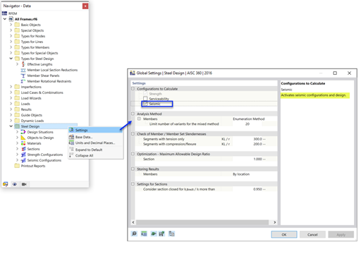
The Steel Design add-on in RFEM 6 now offers the ability to perform seismic design according to AISC 341-16 and AISC 341-22. Five types of seismic force-resisting systems (SFRS) are currently available.


In the ultimate configuration of the steel joint design, you have the option to modify the limit plastic strain for welds.

Using the "Base Plate" component, you can design base plate connections with cast-in anchors. In addition to plates and welds, the design analyzes the anchorage and the steel-concrete interaction.
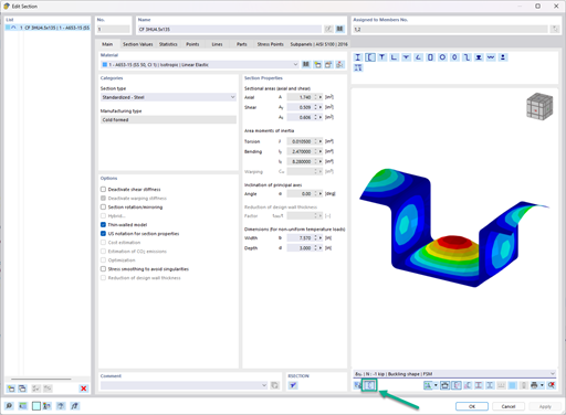
In the "Edit Section" dialog box, you can display the buckling shapes of the Finite Strip Method (FSM) as a 3D graphic.
- Design of five types of seismic force-resisting systems (SFRS) includes Special Moment Frame (SMF), Intermediate Moment Frame (IMF), Ordinary Moment Frame (OMF), Ordinary Concentrically Braced Frame (OCBF), and Special Concentrically Braced Frame (SCBF)
- Ductility check of the width-to thickness ratios for webs and flanges
- Calculation of the required strength and stiffness for stability bracing of beams
- Calculation of the maximum spacing for stability bracing of beams
- Calculation of the required strength at hinge locations for stability bracing of beams
- Calculation of the column required strength with the option to neglect all bending moments, shear, and torsion for overstrength limit state
- Design check of column and brace slenderness ratios
Is it possible to use the general method according to EN 1993‑1‑1, 6.3.4 to design structural components with an asymmetric cross-section in the Steel Design add-on for RFEM 6 or RSTAB 9?
How do I define a plastic hinge in RFEM 6?
How can I exchange data between RFEM 6 / RSTAB 9 and IDEA StatiCa?
How can I generate an area load on members via cells in RFEM 6 or RSTAB 9?
In the Steel Design add-on, I have set the boundary conditions in such a way that the I-beam flange is restrained against the horizontal displacement. I then calculated the critical load factors using the Structure Stability add-on, but with no effect on the critical load factor value. What is the reason for this?
Can I estimate which minimum cross-sections I should use before starting to design my model?


