175 Results
View Results:
Sort by:

Defining the appropriate effective length is crucial in obtaining the correct member design capacity. For X-bracing that is connected at the center, engineers often wonder if the full end-to-end length of the member shall be used, or whether using half of the length to where the members are connected is sufficient. This article outlines the recommendations given by the AISC and provides an example on how to specify the effective length of the X-braces in RFEM.

When it comes to wind loads on building type structures as per ASCE 7, numerous resources can be found to supplement design standards and aid engineers with this lateral load application. However, engineers may find it more difficult to find similar resources for wind loading on non-building type structures. This article will examine the steps to calculate and apply wind loads as per ASCE 7-16 on a circular reinforced concrete tank with a dome roof.

The wind load of rectangular rounded structural components is a complex matter. The equivalent forces from wind load depend on the strength of the circulating wind load and the component geometry.

In Germany, DIN EN 1991-1-4 with the National Annex DIN EN 1991-1-4/NA regulates the wind loads. The standard applies to civil engineering works up to an altitude of 300 m.

Wind blowing parallel to the surfaces of a structure can generate friction forces on these surfaces. This effect is important mainly for very large structures.

The design of a torsional loaded beam according to AISC Design Guide 9 will be shown, based on a verification example. The design will be performed with the RF‑STEEL AISC add-on module and the RF‑STEEL Warping Torsion module extension with 7 degrees of freedom.

According to Clause 6.2.2 (6) of EN 1993‑1‑8:2010‑12, you can apply friction using the friction coefficient to design the shear capacity.

Both the determination of natural vibrations and the response spectrum analysis are always performed on a linear system. If nonlinearities exist in the system, they are linearized and thus not taken into account. They are caused by, for example, tension members, nonlinear supports, or nonlinear hinges. This article shows how you can handle them in a dynamic analysis.

Torsional buckling analysis of transverse and longitudinal stiffeners with open cross-sections is described in DIN EN 1993-1-5, Chapter 9. There is a difference between the simplified method and the precise method, which takes into consideration the warping stiffness of the buckling panel. The simplified method applies Equation 9.3 of DIN EN 1993‑1‑5. If warping stiffness is to be taken into account, either Eq. 9.3 or Eq. 9.4 should be followed. Both design methods are implemented in PLATE-BUCKLING.
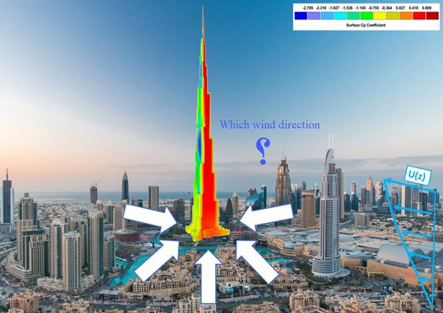
Wind direction plays a crucial role in shaping the outcomes of Computational Fluid Dynamics (CFD) simulations and the structural design of buildings and infrastructures. It is a determining factor in assessing how wind forces interact with structures, influencing the distribution of wind pressures, and consequently, the structural responses. Understanding the impact of wind direction is essential for developing designs that can withstand varying wind forces, ensuring the safety and durability of structures. Simplified, the wind direction helps in fine-tuning CFD simulations and guiding structural design principles for optimal performance and resilience against wind-induced effects.